This note mainly covers the code basics for Shaders created in Unity.
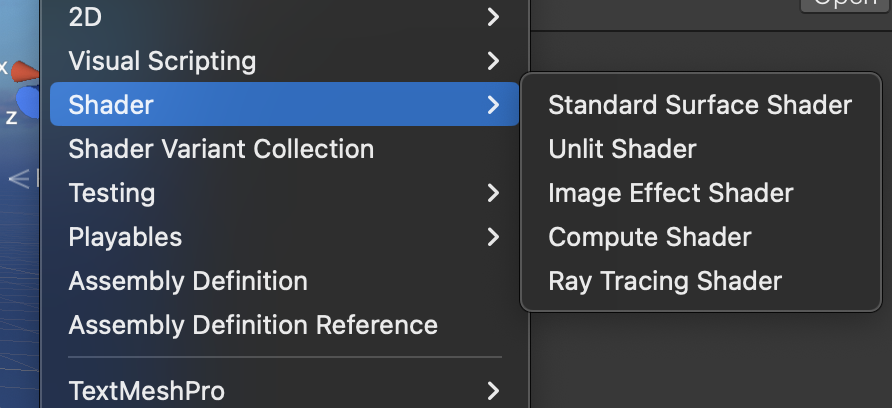
Right-click in the Asset window: Shader > Unlit Shader to create a new Shader file.
Double-click to open this Shader with Jetbrains Rider (Visual Studio is not recommended, as it does not have default word wrap adjusted for shader code).
The following basic framework is the most essential template for Shader code.
Plain TextShader "Name"
{
    Properties
    {

    }

    SubShader
    {
        Pass{

        }
    }
}
Property Attributes
In the Properties section, we can declare new properties using the template in the comments. These properties will appear on the material panel of the material ball that the Shader is attached to, so we can modify them from the Inspector.
Plain TextProperties
{
    //variable name + (the name you want to show in the inspector) + , + type + = + default value

    // Float
    _VariableName("Shown Name", Float) = 0.0

    // Int
    _SomeProperty("Some Property", Int) = 2

    // Range(min, max)
    _Range("Range", Range(0.0, 1.0)) = 0.0

    // Vector
    _Vector("Vector", Vector) = (1,1,1,1)

    // Color
    _Color("Color", Color) = (0.5,0.5,0.5,0.5)

    // 2D
    _Texture("Texture", 2D) = "white" {}

    // 3D
    _Model("Model", 3D) = "black"{}

    // Cube
    _Cube("Cube", Cube) = "white"{}
}
SubShader
The actual shading logic is written inside SubShader. Below is a typical SubShader template.
Plain TextSubShader
{
    // Optional
    Tags {}

    // Optional
    // [Render Setup]

    // A SubShader can contain multiple Pass{} blocks.
    Pass
    {
        // Implement code between CGPROGRAM - ENDCG
        CGPROGRAM
        // #pragma vertex defines a vertex shader named vert
        #pragma vertex vert

        // #pragma fragment defines a fragment shader named frag
        #pragma fragment frag

        // include some header files
        #include "UnityCG.cginc"

        ENDCG
    }
}
For Tag and Render Setup, see Unity Shader#2.1.
Pass Block
Recall the rendering pipeline.
The SubShader corresponds to two parts of the GPU: the geometry stage and the rasterization stage. Pass defines our actual operations.
In Unity, a basic Shader that fulfills the vertex-fragment shader role we discussed should have the following characteristics:
- The vertex shader returns a float4, transforming model-space coordinates to clip-space coordinates.
- The fragment shader returns a float4, outputting the color of that fragment.
The simplest vertex-fragment shader can be written like this:
Plain TextSubShader {
    Pass {
        CGPROGRAM

        // Define vertex shader vert and fragment shader frag
        #pragma vertex vert
        #pragma fragment frag

        // Vertex shader vert returns coordinates, so it is float4
        // Vertex shader input should be model coordinates; POSITION refers to vertex position in model space, a special meaning defined by Unity
        // SV_POSITION refers to vertex position in clip space
        float4 vert(float4 v: POSITION) : SV_POSITION {
            return mul(UNITY_MATRIX_MVP, v);
        }

        // Fragment shader frag returns color, so it is also float4
        // The fragment shader does not necessarily need to receive information from vertices; it only needs to define what color this fragment will display on this pixel
        float4 frag() : SV_Target {
            return fixed4(1,1,1,1);
        }

        ENDCG
    }
}
Vertex Shader
Input: The vertex shader typically receives model-space vertex positions, normals, texture coordinates, etc. This data usually comes from the appdata structure. We can also customize this structure to obtain the specific information we need.
Plain TextSubShader
{
    Pass
    {
        CGPROGRAM
        #pragma vertex vert
        #pragma fragment frag
        #include "UnityCG.cginc"

        // Use appdata to obtain application-stage information
        struct appdata
        {
            // POSITION refers to object vertex coordinates in model space
            float4 vertex : POSITION;

            // TEXCOORD[n] semantics are texture coordinates; n must be unique, multiple texture coordinate sets are allowed
            float2 uv : TEXCOORD0;

            // NORMAL semantics are vertex normal
            float3 normal : NORMAL;

            // COLOR semantics are vertex color
            float4 color : COLOR;

            // TANGENT describes the tangent vector for each vertex
            float4 tangent : TANGENT;

            // VERTEXID is the unique identifier for the vertex
            uint id : VERTEXID;

            // BLENDWEIGHT represents skeletal animation weights
            float blendweight : BLENDWEIGHT;
        };

        ENDCG
    }
}
Processing: Similarly, we can define an output structure from the vertex shader to the fragment shader, typically named v2f (Vertex To Fragment). In this structure, we pass data to the fragment shader. We perform calculations on this data in the vertex shader, usually in the vert function.
Plain TextSubShader
{
    Pass
    {
        CGPROGRAM
        #pragma vertex vert
        #pragma fragment frag
        #include "UnityCG.cginc"

        struct appdata
        {
            float4 vertex : POSITION;
        };

        // vertex to fragment structure
        struct v2f
        {
            // SV_POSITION refers to vertex position in clip space
            float4 pos : SV_POSITION;

            // WORLDPOS refers to vertex position in world space
            float4 worldPos: WORLDPOS;

            // NORMAL refers to the vertex normal vector
            float4 normal : NORMAL;

            // TEXCOORD[n] is similar to appdata
            float2 texcoord : TEXCOORD0;
        };

        ENDCG
    }
}
Output: At this point, we can change the vert function's return value from float4 to v2f, and change vert's input from a simple float4 to appdata. The vert function will output one v2f structure per vertex.
Plain TextSubShader
{
    Pass
    {
        CGPROGRAM
        #pragma vertex vert
        #pragma fragment frag
        #include "UnityCG.cginc"

        struct appdata
        {
            float4 vertex : POSITION;
        };

        struct v2f
        {
            float4 pos : SV_POSITION;
        };

        // Note the difference from the simple vertex-fragment shader above
        v2f vert(appdata v)
        {
            // use o as a shorthand for output
            v2f o;
            float4 pos_clip = mul(UNITY_MATRIX_MVP, v.vertex);
            o.pos = pos_clip;
            return o;
        }

        ENDCG
    }
}
Although there are no for loops anywhere in the Shader code, remember that the vert function operates per vertex. Each vertex of the model is processed by the vertex shader.
Between the vertex shader and fragment shader, there is typically an interpolation step. After the vertex shader finishes, we only have as many v2f structures as there are vertices. However, the fragment shader runs per pixel, and each pixel needs its own v2f structure. Therefore, the number of v2f structures after the vertex shader is clearly insufficient.
At this stage, Unity automatically interpolates v2f data for all pixels that have not been computed. This interpolation is performed based on nearby vertices using a certain algorithm. After this step, each pixel has its own v2f structure.
Fragment Shader
Input: Finally we implement our fragment shader, typically named the frag function. frag receives a v2f as input, which, as discussed above, is an already-interpolated v2f structure. So even though frag runs per pixel, we still compute the pixel color result based on v2f. SV_Target after frag is also a system semantic that stores the user's output color into the frame buffer.
Plain TextSubShader
{
    Pass
    {
        CGPROGRAM
        #pragma vertex vert
        #pragma fragment frag
        #include "UnityCG.cginc"

        struct appdata
        {
            float4 vertex : POSITION;
        };

        struct v2f
        {
            float4 pos : SV_POSITION;
        };

        v2f vert(appdata v)
        {
            v2f o;
            float4 pos_clip = mul(UNITY_MATRIX_MVP, v.vertex);
            o.pos = pos_clip;
            return o;
        }


        float4 frag(v2f i) : SV_Target
        {
            return float4(0.5,1.0,0.5,1.0);
        }

        ENDCG
    }
}
Save the Shader—this is a simple shader that trivially displays a fixed color.
If we want to use variables defined in Properties, we must also declare them in SubShader. The names must match exactly.
Plain TextShader "Unlit/NewUnlitShader"
{
    Properties
    {
        _Color("Color", Color) = (0.5,0.5,0.5,0.5)
        _MainTex("MainTex", 2D) = "white" {}
    }

    SubShader
    {
        Pass
        {
            CGPROGRAM
            #pragma vertex vert
            #pragma fragment frag
            #include "UnityCG.cginc"

            struct appdata
            {
                float4 vertex : POSITION;
                float2 uv : TEXCOORD0;
            };

            struct v2f
            {
                float4 pos : SV_POSITION;
                float2 uv : TEXCOORD0;
            };

            float4 _Color;
            sampler2D _MainTex;
            float4 _MainTex_ST;

            v2f vert(appdata v)
            {
                v2f o;
                float4 pos_world = mul(_Object2World, v.vertex);
                float4 pos_view = mul(UNITY_MATRIX_V, pos_world);
                float4 pos_clip = mul(UNITY_MATRIX_P, pos_view);
                o.pos = pos_clip;
                return o;
            }

            float4 frag(v2f i) : SV_Target
            {
                float4 col = tex2D(_MainTex, i.uv);
                return col;
            }

            ENDCG
        }
    }
}